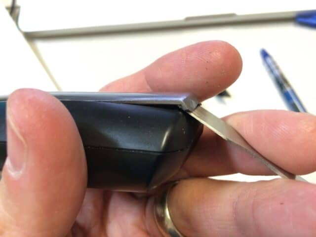
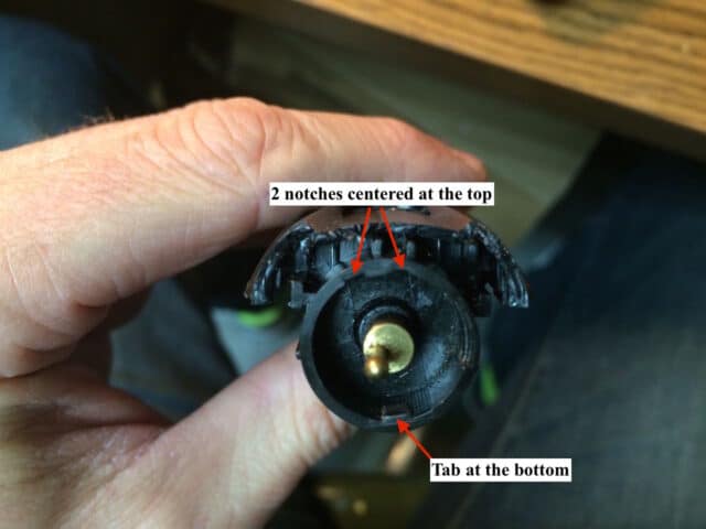
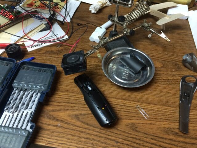
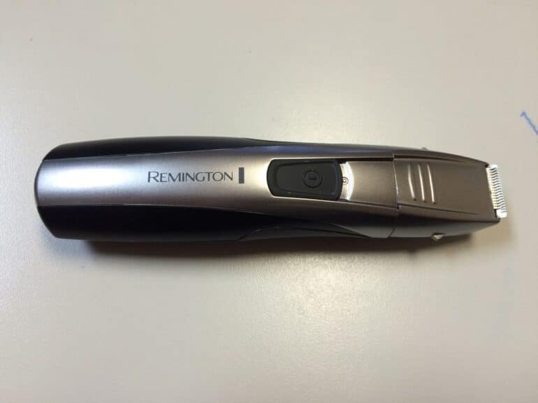
Twist the end counter-clockwise just enough to unlatch the head, according to the unlock arrow pictured below and then pull the trimmer head off.
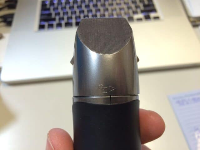 |
| Twist the trimmer head counter-clockwise about a quarter inch to unlatch it and then pull it off |
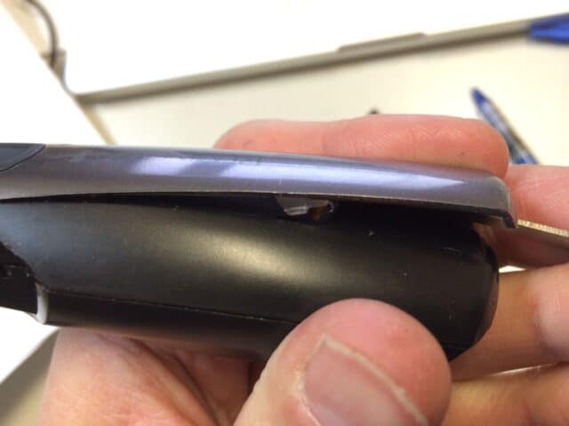
Here’s what you’ll have when you get it off:
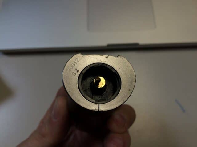 |
| Trimmer head removed |
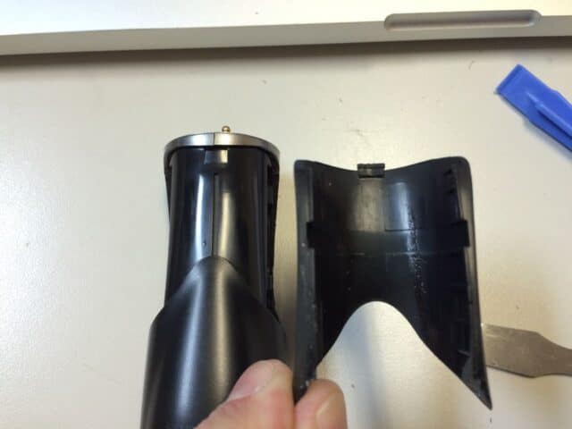
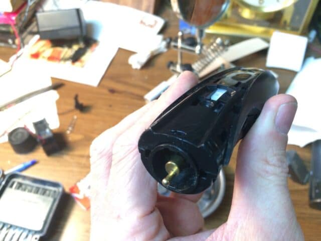
Step 2: Remove the rubber grip. This piece is plastic covered in rubber and wraps about 300 degrees around the trimmer body:
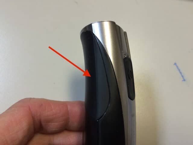 |
| Rubber grip piece |
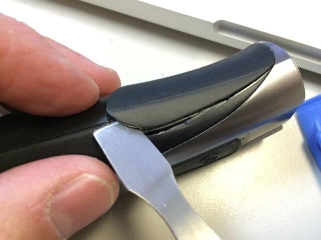
I used a pry tool I received with an iPhone display I purchased to fix a friends iPhone 4S. Important note: the rubber grip piece has a tab that tucks under on the trimmer end so don’t pry on that end–pry on the sides. Here is where you need to pry on both sides:
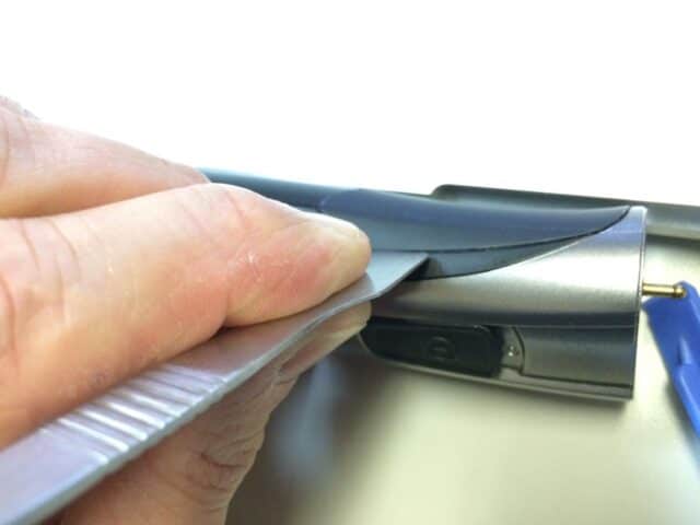 |
| Prying off the rubber grip |
Here’s what it looks like when it starts to pry up:
 |
| The rubber grip is popping off |
And finally off:
 |
| Rubber grip removed (see the tab on the top) |
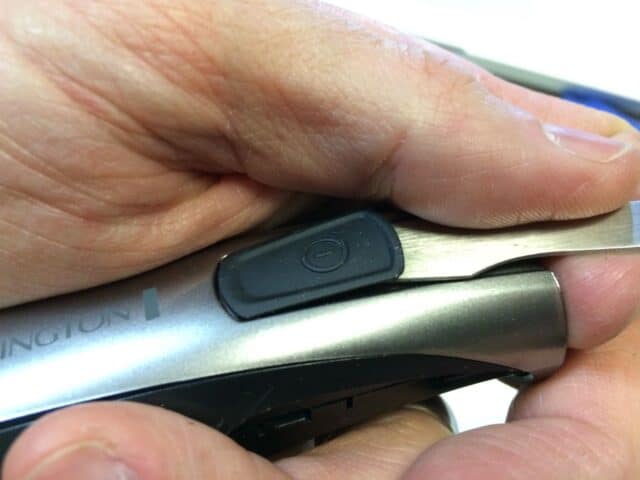
Step 3: Pry off the power button slider.
There’s a hidden screw under there that we must remove. It snaps straight down onto the body of the trimmer. Pry it off like this:
 |
| Prying up the power slider |
Here’s the power button slider removed. Note that the two outside tabs are what snaps it in place and the middle tab is what sits down into a white plastic piece that runs to the switch.
 |
| Power button slider removed |
Step 4: Remove the screw that was hidden under the power slider button.
There it is:
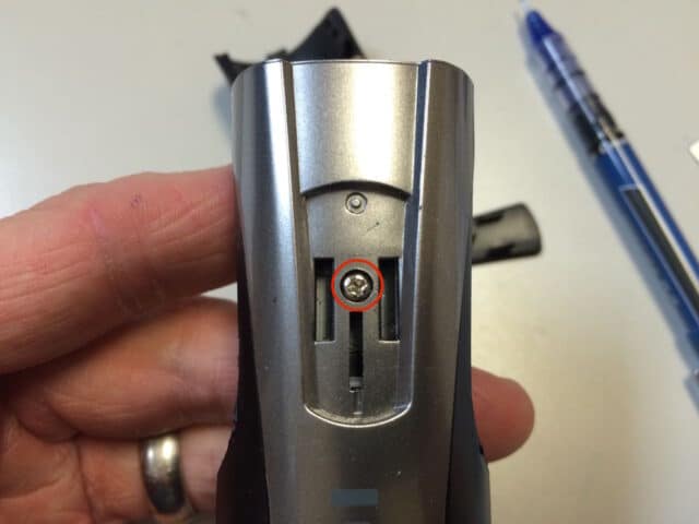 |
| Screw location under power slider button |
Step 5: Pry off the center plastic panel.
Start at the end by where the power plug goes:
 |
| Prying off the center silver plastic panel–start on the end |
It will begin to come up:
 |
| Prying off the center silver panel |
The sliver piece loops around the other end so be careful when removing it. And here’s the piece removed:
 |
| Silver plastic panel removed |
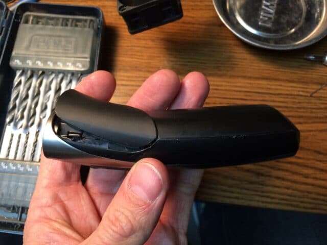
Some of the black body broke off when I was taking off the silver panel. I’m not sure what caused that but you can see it here (and it wasn’t glued to the silver piece):
 |
| The edge of the black body broke off |
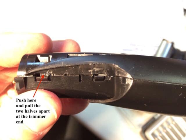
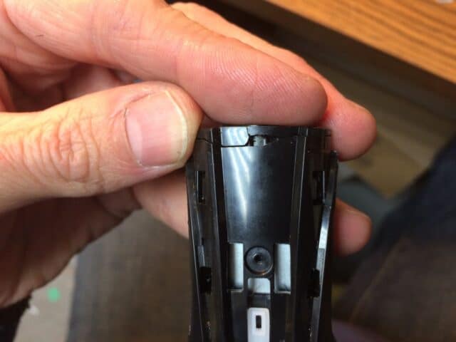
Step 6: Pry the two halves of the body apart.
There are two large tabs under where the rubber grip was that need to be unlatched. The one on the trimmer end is marked in the picture below. There is one on each side and you should unlatch them first.
 |
| Separating the halves, part 1 |
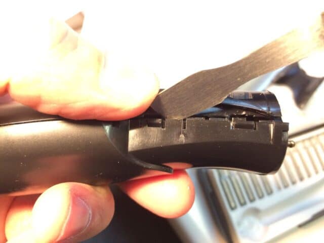
Once you have the first two tabs unlatched you can unlatch the next to as shown below:
 |
| Prying the second tab free |
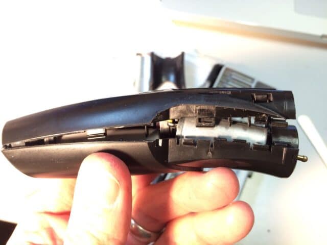
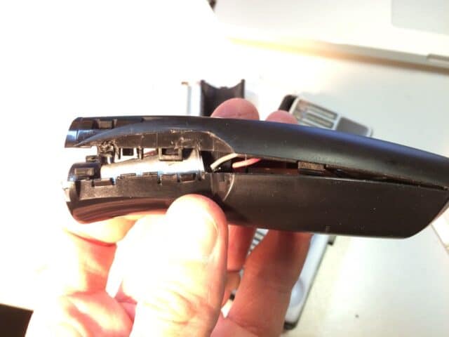
Once you get the four main tabs freed this is what you’ll see:
 |
| The two halves freed, left side |
 |
| The two halves freed, right side |
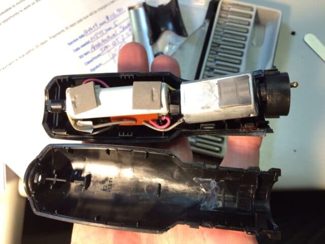 |
| Two halves separated |
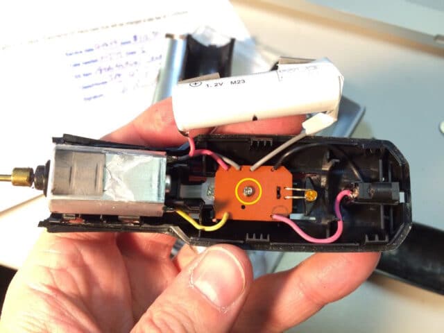
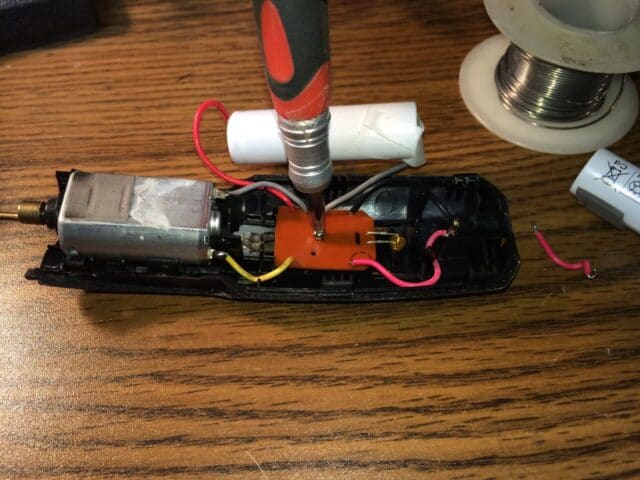
Step 7: Remove the screw securing the circuit board.
Lift out the battery as seen below. It isn’t secured in place and simply fits down into a trough created by the plastic body.
 |
| Circuit board screw location |
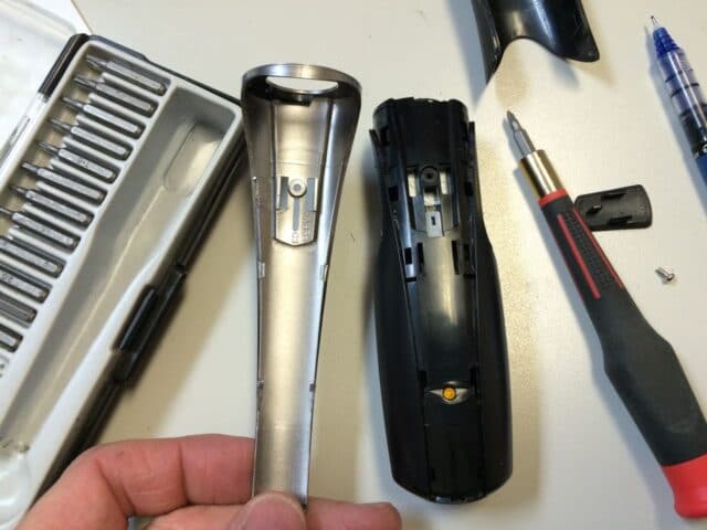
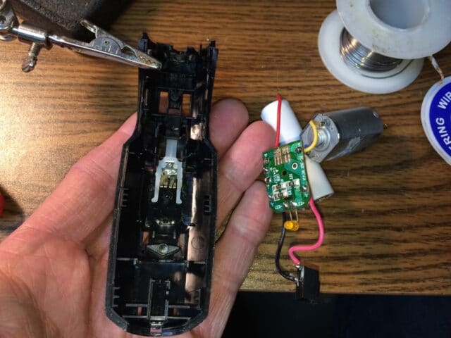
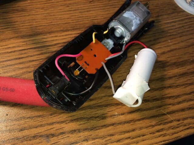
Once you remove the screw you can take the motor, circuit board, battery and power plug out of the trimmer body:
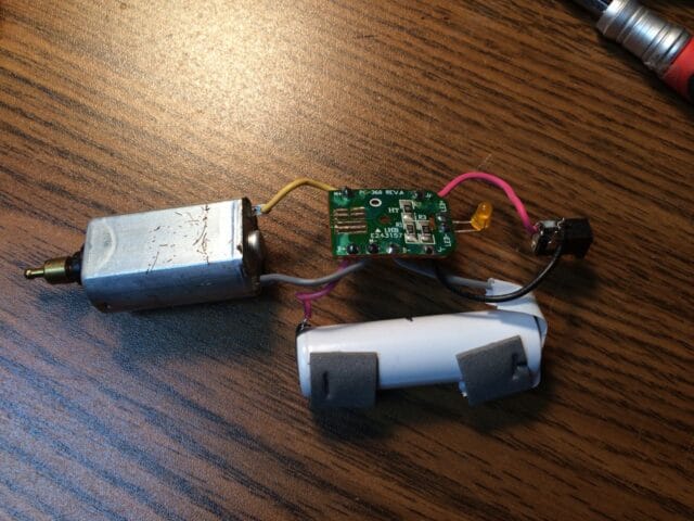 |
| The trimmer insides removed |
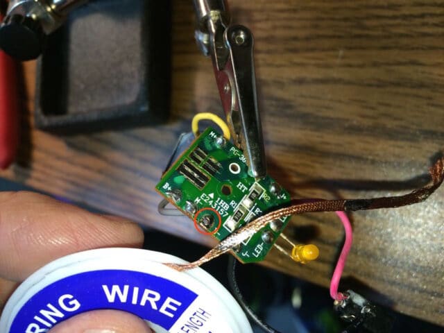
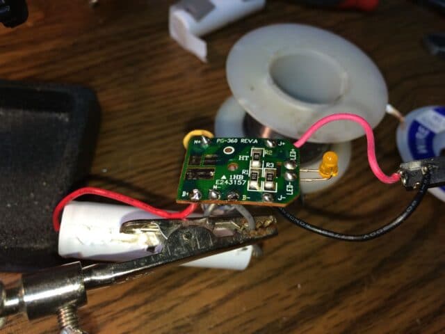
Note the battery connections on the circuit board are labeled B+ and B- for the positive (+) and negative (-) terminals of the battery, along with the red wire standing for positive which is common:
 |
| Add caption |
Step 8: Remove the old battery.
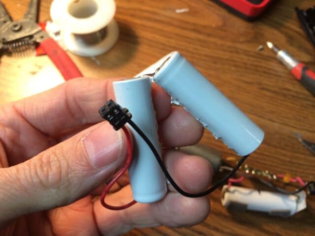
Now if you purchased the replacement battery I have linked at the top of this page then you should unsolder the battery wires from the tabs on the old/original battery and solder the new battery to the original wires. Those wires pass through a hole in the tab so you’ll need to heat the solder up and then pull them out. I actually used half of a NiCad battery pack I had on hand and separated the two batteries:
 |
| NiCad 2-AA battery pack |
I pealed off the plastic shrink wrap and then separated the two batteries that were glued together (I had to use a pocket knife because they were glued together):
 |
| Batteries separated |
I then cut the tab that connected the two cells. I wanted to use the existing tab to solder the old lead back on so if you do it this way be careful not to pull the spot welds off the end of the battery.
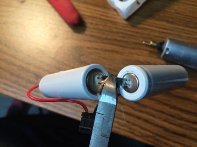 |
| Cutting the metal tab in half |
I used my “extra set of hands” to hold the battery while I was soldering (clipped to a piece of duct tape I put on the battery to give it something to grab onto):
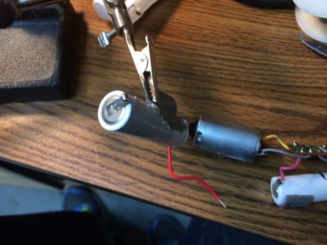 |
| Put some solder on the metal tab to prep it for soldering the wire on it |
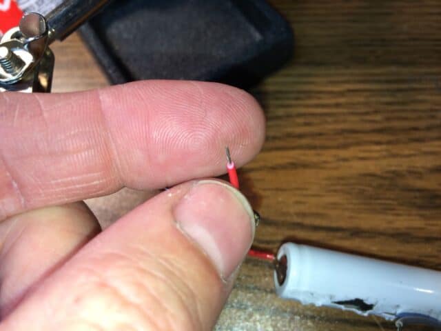
To unsolder the wires from the circuit board, heat up the solder joint while pulling on the wire:
 |
| Old battery unsoldered |
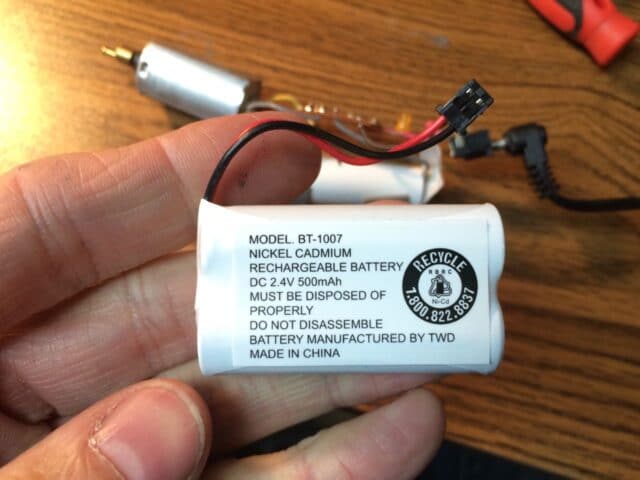
Here’s the battery details:
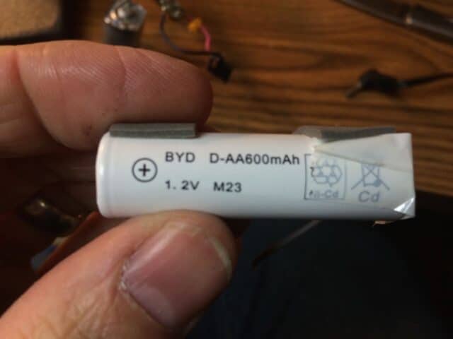 |
| Battery details: BYD D-AA600mAh 1.2V M23 |
The original battery is 600mAh, the two pack I am using is 2.4V and 500mAh. At 1.2V, each cell will also be 500mAh, so this battery will have slightly lower capacity (20% lower) than the original but it’s what I had on hand so that’s what I went with. It’s nice when you can repair something with parts on hand 🙂
I then removed the solder from the battery connections on the circuit board using solder wick. To do this simply press the solder wick against the solder with a hot soldering iron tip and when the solder begins to melt it will be drawn up into the solder wick.
 |
| Solder removed from the negative connection |
 |
| Solder removed from the positive connection |
Step 9: Install the new battery.
Depending on if you are using the battery I link to in at the top or if you are doing it the way I’m doing it with a scavenged battery, your steps will vary. In my case I first soldered the old negative wire onto the new battery (on the end that had the tab). I used the positive wire on the other end that was already connected to the battery:
 |
| Old wire soldered onto new battery |
I then cleaned a little of the insulation off the end of the positive wire. I then lightly tinned the bare wire. Tinning is melting solder into the wire, which aids in making a quick solder connection. If you put too much solder on it, it will not go through the hole on the circuit board (which was the case for me the first time I tried it):
 |
| Here I’m about to “tin” the end of the positive wire on my new battery |
Insert the new wires into the correct polarity of hole in the circuit board and solder in place. If you are using the battery I linked in the description you would not be doing this but you would be soldering the old/existing wires to the new battery.
 |
| New Battery soldered in place |
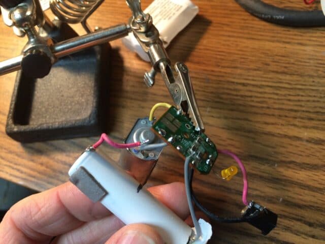
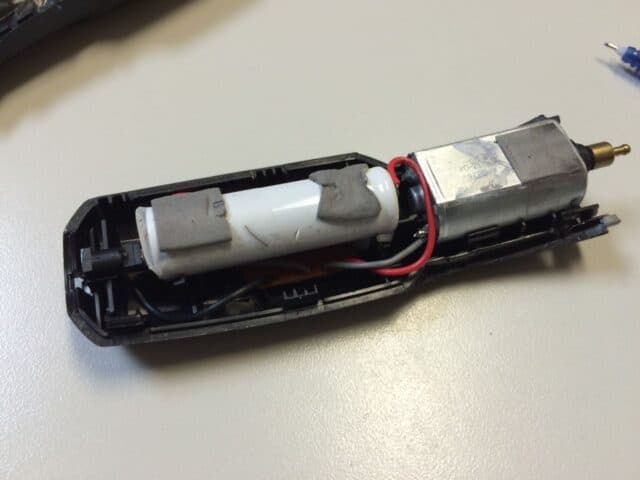
Step 10: Reinstall the “insides” of the trimmer.
Line up the LED with the hole in the case and insert the power plug into the slot made to hold it in the case, and then nestle the battery down into the two u-shaped slots in the case designed to hold it:
 |
| Time to install the guts |
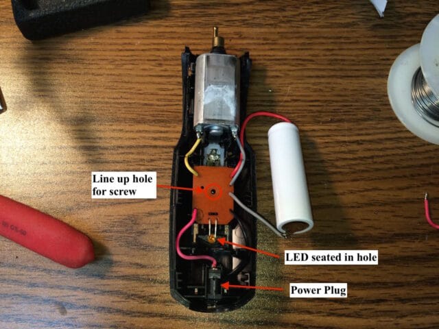 |
| Location of parts |
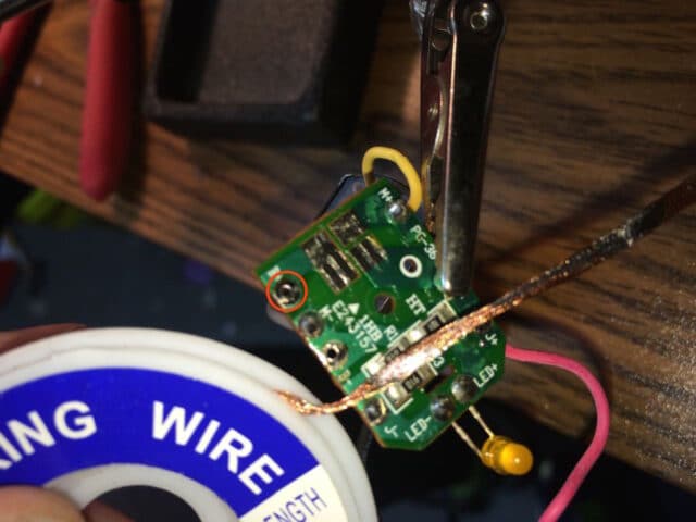
Once you have everything lined up, reinstall the screw into the circuit board.
 |
| Reinstalling the circuit board screw |
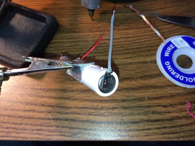
Because of the proximity of the negative end of the battery to the power plug, there originally was a piece of tape over the end of the battery. I transferred this over to the new battery:
 |
| Tape applied to new battery |
Step 11: Seat the battery in the case.
There are two trough-shaped plastic tabs that stick up that the battery sits down on. Once you have the battery seated, transfer the foam stickers onto the top of the new battery as seen below:
 |
| Battery re-seated into case and the foam pads transferred over |
Step 12: Partially put the second half of the case onto the trimmer.
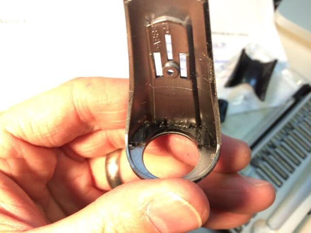
Don’t snap it together though because we need to install a little round plastic piece on the end that surrounds the motor shaft and is what the trimmer head locks into. This is what you should have:
 |
| Case partially re-assembled but not snapped together on the trimmer head end |
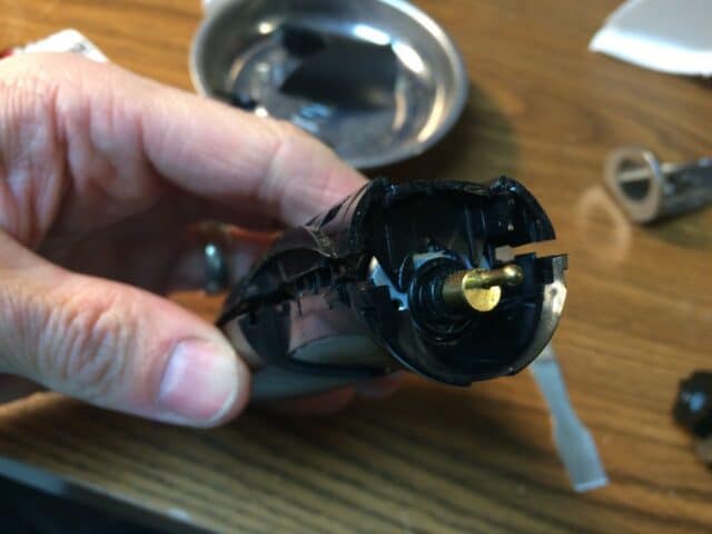
Step 13: Reinstall the black round plastic end that the cutter head assembly snaps into.
I wasn’t sure which way to orient this piece at first because part of the black case had broken off when I disassembled the trimmer so I installed the trimmer head and compared it to the original pictures to figure it out.
 |
| Orientation of round plastic part that slides over the shaft |
Step 14: Snap the case together.
Pay attention to the seams to make sure that the correct edge is tucked under the other edge. This is what you should have:
 |
| Case snapped together |
Step 15: Glue the case, if necessary.
Somehow the top edge of the black case broke off when I disassembled this trimmer so once I had the case all snapped together I super glued the two pieces back on:
 |
| Super gluing the two pieces back on the edge (and these pieces help hold the round part on the end) |
I used a scavenged case fan to help the glue dry faster. Read about how to power scavenged fans on my post here: How to Power a Scavenged Fan with a Used Wall Plug
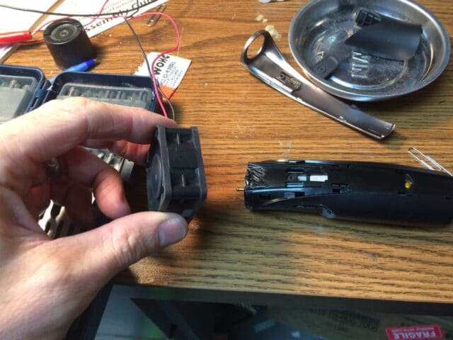 |
| Drying the glue with a scavenged case fan |
Here’s another good reason to have an Extra Set of Hands Magnifier Tool , to hold your fan for you:
 |
| Holding the fan with my extra set of hands |
Step 16: Reinstall the silver center panel.
It loops over the end of the trimer and then snaps into place. Here I’m about to snap it down into place:
 |
| Reinstalling the silver center panel |
After you snap the silver panel down, reinstall the screw:
 |
| Reinstalling the center silver panel screw |
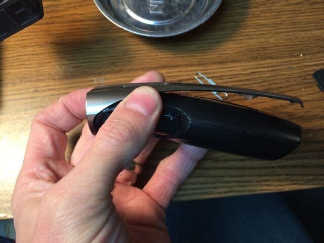
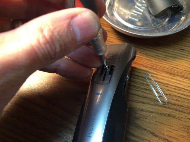
Step 17: Reinstall the power slider button.
First you’ll want to line up the white plastic piece that the power slider button sits down into. When I got to this point the rectangular slot in the white inner plastic piece was hidden under the case. I used a straightened paperclip to move it into view:
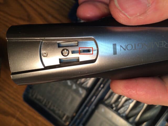 |
| Rectangular slot in white plastic part is fully in view (in off position now) |
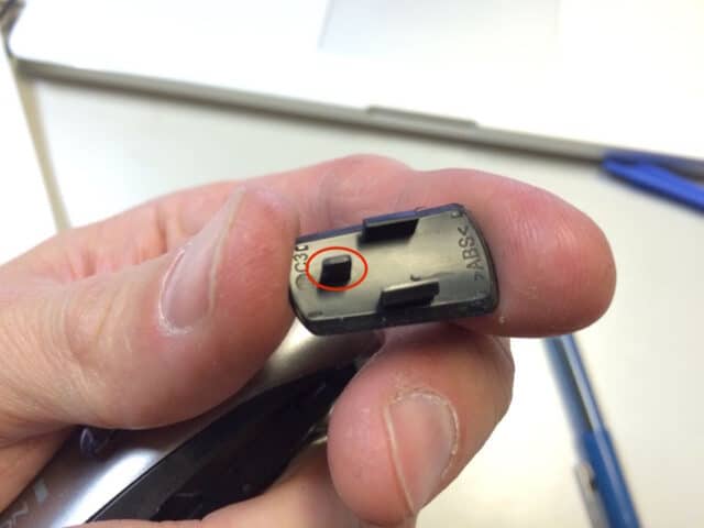
The tab that sticks out on the back of the switch (circled below) goes in the hole seen above.
)
(replacement for stock BYD D-AA600mAh 1.2V M23)

Really found this helpful with getting ready to do a repair. Like the previous comment…Would like to convert to a AC-powered trimmer only. Or to swap out the rechargeable battery for standard AA batteries.
Thanks for the detailed explanation. The explanation was very clear and you made it really easy for me to repair my beard trimmer! Thanks a lot!
Wondering if i can replace the Ni-CD with a Nimh battery and still use the same charger
I have heard that you can, in fact, swap out NiCD’s with NIMH’s. I think it will take a couple cycles to get the new batteries fully charged though.
Thanks. This is exactly what I needed. New battery installed, all body limbs intact.
Glad you were able to fix your trimmer Aaron, thanks for sharing.
Thanks, that got me going. Forgot to put the rubber pads back on the battery but am not taking it apart again for that.
Thanks! This is perfect, now I just need to know how to make it a plug model.
Thanks for your comment Nathan. Let me see if I understand you correct–you are interested in converting your trimmer into an AC-powered trimmer only, without a battery?